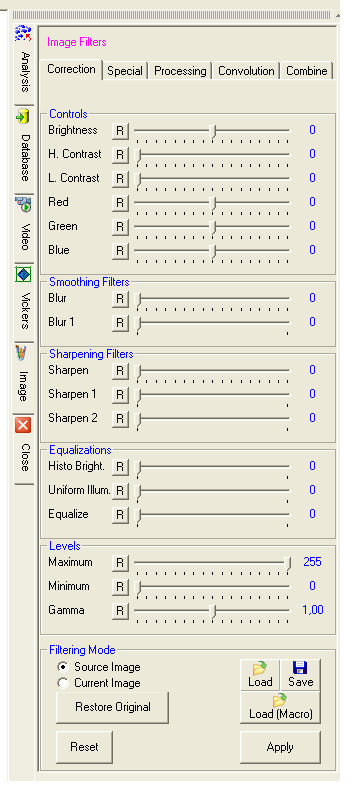
Each filter is applied in real time to the whole image or to part of the image as defined in the Edit menu. The other X-Pro functions can be applied to the resulting image.

Allows you to modify the brightness of the active image.
 CONTRAST - SATURATION
Allows you to modify the contrast and the saturation of the active image.
Allows you to modify the three Red, Green and Blue components of the active image.
Automatic filter for blurring the image. It softens the image: useful for blurring the pixels of zoomed images.
Filter for blurring the image.
Filter for low sharpening of the image. Useful to increase the image definition.
Filter for higher sharpening of the image.
Filter for adjustable sharpening of the image.
Automatic equalization filter.
Automatic equalization filter. It corrects non-uniform illumination of the image.
Automatic equalization filter. It spreads the levels of the image more evenly.
(selectable from the Image Menu)
Filter for automatic correction to white.
If there is an area of the image that needs to be white, you just have
to indicate this point to make a color correction.
Maximum
Sets to white the areas of the image with levels of brightness higher than the threshold level (for color images it is the areas where RGB pixels have values higher than the threshold level).
Minimum
Sets to black the areas of the image with levels of brightness lower than the threshold level (for color images it is the areas where RGB pixels have values lower than the threshold level).
Gamma
Gamma correction of the image.
Original Image
The selected filters are automatically applied to the original image (the image when loaded into the work environment). By clicking on the Apply button the selected filter can be applied to different images.
![]() The buttons
The buttons
![]() reset the corresponding filter. The Reset button
restets all filters.
reset the corresponding filter. The Reset button
restets all filters.
Current Image
The selected filter is applied in real time to the active image in the current state.
![]() The buttons
The buttons
![]() reset the corresponding filter. The Reset button
restets all filters.
reset the corresponding filter. The Reset button
restets all filters.
Restore Original
Cancels the filtering effects and restores the original image.
Load (Macro)
Allows you to load automatically the filter configuration during the runnung of a macro. Use this button during the recording of a macro to select the filter configuration to be used. Using the Load button instead of Load (Macro), the running of the macro will be interrupted and you will be asked to select the configuration file to be used.
Save
Saves the filter configuration for future use.
To be able to define Optical Density it is necessary to define the concept of Transmission.
Transmission (T) is defined as the ratio of transmitted light to incident light expressed as a percentage.
T = (transmitted light) / (incident light) in (%)
![]() If it
is expressed as a ratio it is called Trasmittance.
If it
is expressed as a ratio it is called Trasmittance.
Optical Density (O.D.) is defined as the logarithm to the base 10 of the inverse of Trasmittance:
O.D. = - log (1/T)
Optical Density's range of values goes from zero (100% of transmission) to infinity (0% of transmission) for a totally opaque material.
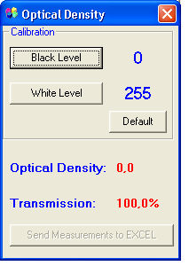
To be able to measure optical density you need to calibrate the system with two images:
image of a totally opaque material (to calibrate the black level);
image without sample (totally trasparent) to calibrate the white level.
Calibration:
acquire the first image and press the Black Level button;
acquire the second image and press the White Level button.
Once the calibration has been performed, acquire the image to be analyzed and select the Optical Density option from the Image menu.
The Optical Density dialog will be displayed again with the measured value.
![]() The system will remain calibrated
until the light intensity in the lighting system is modified.
The system will remain calibrated
until the light intensity in the lighting system is modified.
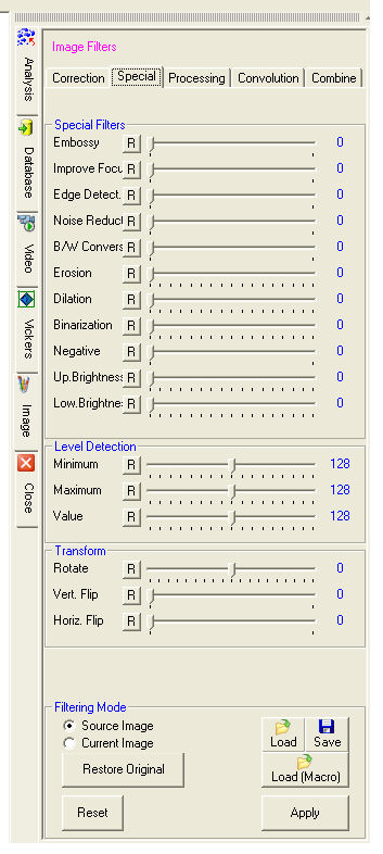 SPECIAL filters:
 Produces a three-dimensional effect of the image.
Combination of filters to improve the focus of an image.
Highlights the boundaries of figures.
Removes isolated pixels whose brightness is notably different from that of neighboring pixels.
The image is reproduced in black and white.
Spreads the light areas of the image.
Spreads the dark areas of the image.
The image is displayed in black and white according to the brightness value defined by the threshold value.
The image is converted into its color negative.
Allows you to highlight the areas of the image above a certain brightness value.
Allows you to highlight the areas of the image below a certain brightness value.
Enables you to highlight the areas of the image within a certain range of brightness.
Allows you to combine the in-focus areas of two images. You are requested to specify the numbers identifying the source image and the second image, which is also the destination of the filtered result.
Allows you to add two images pixel by pixel. You are requested to specify the numbers identifying the source image and the second image, which is also the destination of the filtered result.
Allows you to subtract two images pixel by pixel . The filter can be
used to highlight the space variations in a sequence of images. The unmodified
areas will appear black unlike the modified areas.
You are requested to specify the numbers identifying the source image and
the second image, which is also  the destination of the
filtered result.
the destination of the
filtered result.
Allows you to add two images bit by bit according to the OR rule (1+0=1, 1+1=1). You are requested to specify the numbers identifying the source image and the second image, which is also the destination of the filtered result.
Allows you to multiply two images bit by bit according to the AND rule (1x0=0, 1x1=1). You are requested to specify the numbers identifying the source image and the second image, which is also the destination of the filtered result.
Allows you to add two images bit by bit according to the XOR rule (0+0=0,
1+0=1, 1+1=0). The filter can be used to highlight the radiometric variations
in a sequence of images. The unmodified areas will appear black unlike
the modified areas.
You are requested to specify the numbers identifying the source image and
the second image, which is also the destination of the filtered result.
Allows you to superimpose on the second image the areas of the source
image that exceed the brightness value defined by the threshold.
You are requested to specify the numbers identifying the source image and
the second image, which is also the destination of the filtered result.
Allows you to superimpose the source image on the second image according
to the weight defined by the threshold value.
You are requested to specify the numbers identifying the source image and
the second image, which is also the destination of the filtered result.
Each image pixel is multiplied by the chosen factor.
The image can be rotated by indicating the value in degrees.
The image is flipped horizontally.
The kernel size can be selected among the following pixel combinations: 3x3, 5x5, 7x7 and 9x9.
![]() Enhance are powerful filters
for improving the image.
Enhance are powerful filters
for improving the image.
Each filter can be modified by the user and saved as a new filter (3x3 and 5x5 pixels only).
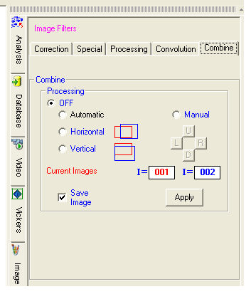 combine images
Combine Images allows you to create a montage of images.
Two modes are available: manual and
automatic.
Open at least two images that you wish to combine. Specify in Source the two numbers identifying the images.
![]() The number identifying the image
is indicated in the image
title bar (e.g., I=001, etc.).
The number identifying the image
is indicated in the image
title bar (e.g., I=001, etc.).
In Processing select Manual.
Drag from the title bar one of the two images until the borders
of the two images overlap.
The  buttons allows you to move the image pixel by pixel for
a perfect superimposition.
buttons allows you to move the image pixel by pixel for
a perfect superimposition.
Then press Apply. A new image will
be created containing the two previous images superimposed.
![]() This new image can be used again
to repeat the Combine Images procedure with another image. The sequence
can be repeated, limited by the system's memory, until the maximum resolution
of 32.000x32.000 pixels is reached.
This new image can be used again
to repeat the Combine Images procedure with another image. The sequence
can be repeated, limited by the system's memory, until the maximum resolution
of 32.000x32.000 pixels is reached.
If the Save Window check box is selected the Save dialog will appear.
Open at least two images that you wish to combine. Specify in Source the two numbers identifying the images and maintain the position of the colors, for example, red to the left and blue to the right. Select the Horizontal or Vertical orientation and press Apply. A new image will be created containing the two previous images superimposed.
![]() This mode can be used to compose
an image with one orientation. To obtain good results the area with a
common border must be about 5-10%. The images must be illuminated as uniformly
as possible.
This mode can be used to compose
an image with one orientation. To obtain good results the area with a
common border must be about 5-10%. The images must be illuminated as uniformly
as possible.
If the Save Window check box is selected the Save dialog will appear.
Example
Image from electronic microscope (SEM)
Aim: Enhance the view of the atomic planes to measure their distance.
Open the image acquired with SEM;
By clicking at the Select Part of Image
option in the Edit menu, define
the portion of the image to which you want to apply the Fourier transform.
From the Image menu
select Fast Fourier Transform
(FFT IFFT).
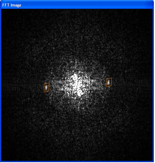
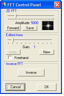
Press the Forward button in the FFT Control Panel dialog.
![]() The Amplitude slider controls the brightness of the Fourier transform
but this adjustment has no influence over the final result of the filter's
processing. It only allows a better view of the FFT. For a new Amplitude value
you need to press Forward again.
The Amplitude slider controls the brightness of the Fourier transform
but this adjustment has no influence over the final result of the filter's
processing. It only allows a better view of the FFT. For a new Amplitude value
you need to press Forward again.
Circumscribe with the mouse the regions of interest in the FFT window.
![]() The regions can be defined either
with polygons or in freehand if the Freehand check box is selected.
The regions can be defined either
with polygons or in freehand if the Freehand check box is selected.
Double-click to close the regions.
If greater than one, the Gain amplifies
the frequencies of the selected regions. Set the value to 5000.
Apply the chosen gain and the result will be displayed in the FFT
window.
![]() The New button allows you to define new regions on which to apply
a gain different from the previous one. Filterings
with different gains can then be performed on different frequencies.
The New button allows you to define new regions on which to apply
a gain different from the previous one. Filterings
with different gains can then be performed on different frequencies.
Inverse performs the Inverse
Fourier Transform showing the result inside the rectangle of interest
of the unfiltered image.
Cancel stops the filtering and terminates the function.
If you wish to apply a new filtering, press Forward
again and the previous result will be deleted and a new cycle started.
OK fixes the current result on the image and terminates the function.
|
Image before filtering
|
Image after filtering
|
|
|
|
Creates a new image by merging all the open images.
This function is particularly useful for fluorescence applications.

